Large Aspheres: Enabling High-Power Optical Systems
The drive towards higher power lasers in optical applications is pushing the limits of optical coating technology. However, an alternate solution for handling higher power beams is to increase beam diameter, which requires larger optical components (Figure 1). This decreases the power or energy density across the optical components, reducing the likelihood of laser-induced damage. Large beam expansion optics and focusing lenses further down the beam path are required. Light collection systems are another driver for increasing optics size. A greater amount of light can be collected by optics with a larger surface area. In both of these scenarios, and numerous others, the performance of the optical system can also be increased by using aspheric lenses instead of spherical ones. In years past, optical designers may have had reservations about using aspheric lenses with diameters exceeding 100mm because of the difficulty of making and measuring aspheres that large. However, more recent advances in the fabrication and metrology of aspheric surfaces has allowed aspheres as large as 200mm in diameter to be commercially available, like the TECHSPEC® 200mm Diameter Precision Aspheric Lenses.
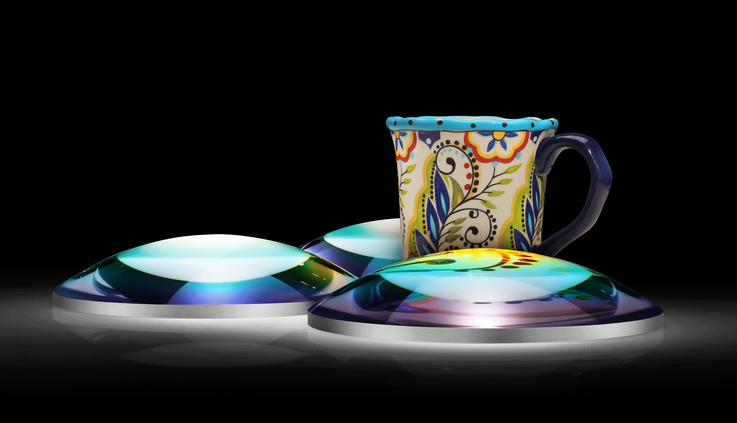
Figure 1: Large diameter aspheric lenses are increasing in popularity, though they pose several manufacturing and metrology challenges not found in standard-sized aspheres.
What Exactly Does “Large” Mean?
In order to properly discuss large aspheres, it is necessary to make a distinction between “large” and “very large” aspheres. “Very large” lenses are too big for one person to carry by hand. Mechanical supports are needed to move them, which presents even more difficulties and requires thorough up-front planning of their fabrication and metrology process. Additional considerations and limitations are associated with these lenses beyond those for typical aspheric lenses and this article focuses on the manufacturing of “large” mass-produced aspheres that can still be carried by a single person.
Manufacturing Considerations
To determine how the following considerations may impact the size or cost of custom aspheric lenses, please contact us.
Diameter
The diameter of the optics that can fit in a grinding and polishing machine is a clear limit when making large aspheres. Thankfully, the names of many computer numerical control (CNC) grinding and polishing machine models describe that machine’s range of motion. For example, “CNC200” often implies that the machine has a 200mm range of motion, while “CNC100” would have a 100mm range of motion. However, this does not mean that “CNC200” could manufacture a 200mm diameter asphere.
The maximum optic size that a machine can make is limited by both the machine’s kinematics and the optic’s shape. At the beginning of asphere fabrication, an oversized blank is used and later edged down to the desired end diameter towards the end of the manufacturing process. Consider a lens blank in the center of a polishing machine on a spindle. A spinning disk tool is moved radially across the part from one edge to another and the vertical height of the tool is adjusted to form the asphere’s shape. As seen in Figure 2, for a convex lens, the tool has to travel horizontally further than the diameter of the lens. Therefore, the machine’s range of motion would need to exceed the lens diameter.
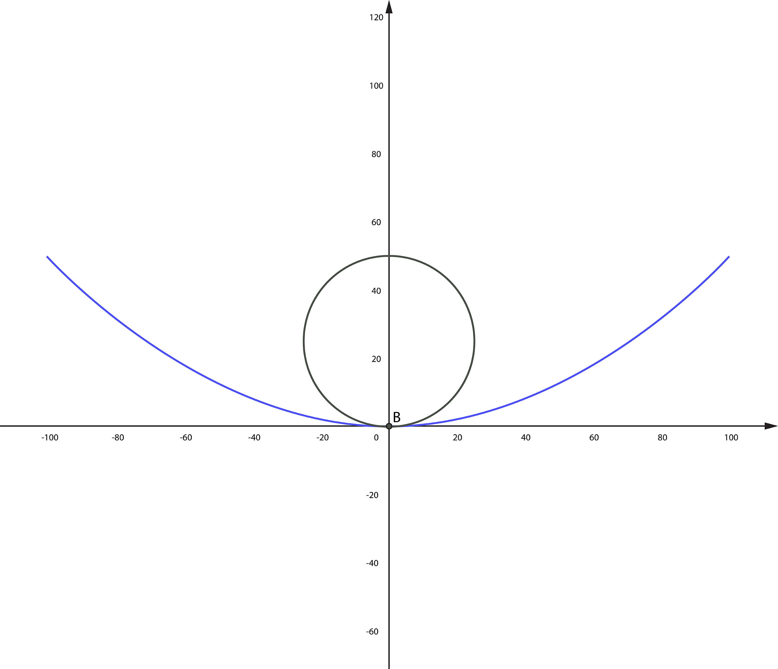
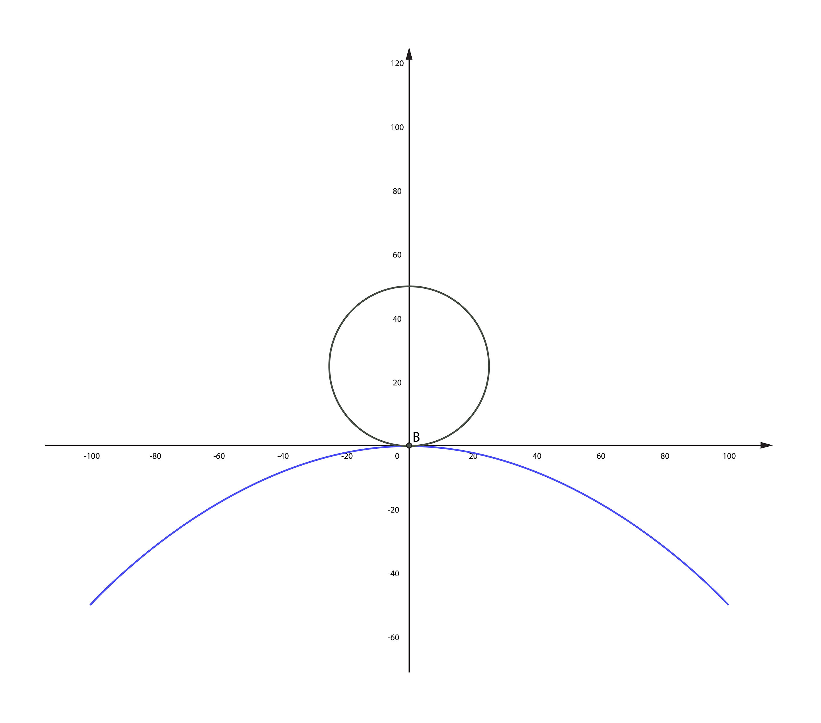
Figure 2: Convex surfaces (b) require a greater horizontal range of motion than concave ones (a) during grinding and polishing.
Some parameters could be adjusted to slightly increase the range of motion, though these tweaks typically result in trade-offs of quality or cost. For example, in the above case, the diameter of the spinning disk tool could be reduced to decrease the range of motion required, but this would decrease polishing speed while increasing polishing time and tool wear. Because of these trade-offs, grinding and polishing machines will not necessarily have hard cut-offs for what size parts are feasible. Instead, they will have a region at which fabrication transitions from straightforward and economical to expensive, and then to not feasible.
Weight
Fabrication machines also have a limit on the maximum weight they can handle, which obviously increases as component diameters expand. While limits vary from machine to machine, the motors controlling the spinning or translating of the lens must be able to generate enough torque to complete their task. Machines may need to be specifically configured for heavy optics, often resulting in increased cycle times and, therefore, higher cost. Optics are also typically adhered to a carrier for simple transfer and alignment during fabrication, which adds additional weight.
Metrology Considerations
Diameter
All equipment used for metrology must also be able to inspect the entire surface of large diameter optics. Similar to the considerations discussed for manufacturing, the metrology tool needs to have a range of motion sufficient to cover the full clear aperture of the lens.
Sagittal Height
Asphere profiles are typically measured during the manufacturing process using a tactile profilometer for iterative feedback. As asphere diameter increases, the sagittal height, or the thickness of the curved surface, will likely increase, though this varies based on the specific asphere design. The height of the stylus used by the tactile profilometer may also limit the sagittal height that can be measured and Figure 3 demonstrates how this can impact the profilometer’s extension beyond the vertex of a convex surface to measure the surface profile on the far side of the lens.
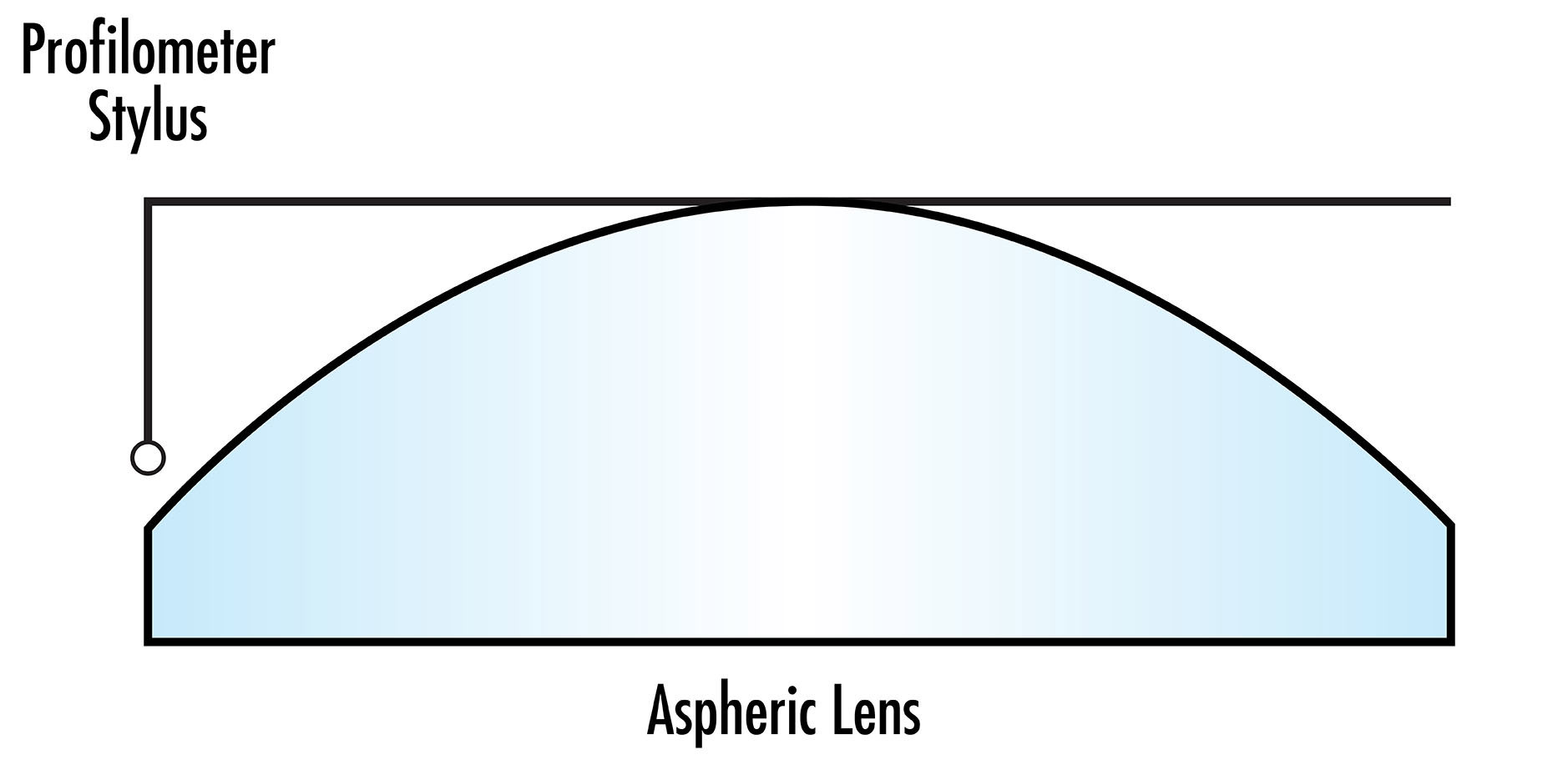
Figure 3: The stylus of a tactile profilometer used for asphere metrology may limit the sagittal height that can be measured for large aspheres.
A similar limitation could impact the metrology of concave surfaces. Optical fabrication engineers can again make some tweaks to process parameters to slightly increase the tool’s range of motion, but these tweaks also often result in trade-offs in quality, cost, or lead time.
Measurement Accuracy
Furthermore, using a larger stylus to alleviate the issue described above may negatively impact the accuracy of the measurement. Increased stylus weight and resulting flex and instability can lead to poor metrology performance.
Considerations for Non-Aspheric Surfaces
Back Surfaces
The back surfaces of aspheric lenses are typically planar or spherical. While the back surface normally has a small influence on the overall cost and manufacturability of an asphere, this changes for large aspheres. Clearly, grinding, polishing, and metrology for this back surface also need to have the required range of motion to cover the part. The metrology can be especially challenging, as large aperture interferometers are typically used for measuring similar planar surfaces. Since Edmund Optics® also manufactures planar optics including windows, prisms, and beamsplitters, equipment used to measure those types of optics is utilized for planar back surfaces of aspheres. Many asphere manufacturers may not have a standard solution for measuring planar surfaces larger than 6 in.
Metrology options are even more limited for convex spherical back surfaces. Large transmission spheres and large aperture interferometers are needed and may be cost-prohibitive or unavailable for many optics manufacturers. For both concave and convex spherical back surfaces, increasing lens diameter corresponds with an increasing radius of curvature (RoC). During interferometer measurements, the range of RoC that can be measured is limited by the length of the interferometer rail. The optic is usually translated on the rail between the cat’s eye position (the spot at which the interferometer beam makes contact on the surface at a single point) and confocal position (the spot at which the interferometer beam’s point focus is collocated with the RoC).
Also, test plates used for in-process metrology become cumbersome and difficult to use for large aspheres. The above manufacturing and metrology considerations also apply to the making of the test plates.
The back surface of the lens could be measured using the same equipment used to measure the aspheric surface, but this process is more expensive and inefficient. The planar or spherical surface would take time away from that more complex metrology that would otherwise be spent on aspheric surfaces. Asphere metrology is typically more time-consuming and requires more skilled optical fabrication engineers. This makes it impractical to use the same metrology for both sides of the lenses.
Diameter
Aspheres are edged down to their final diameter towards the end of the manufacturing process. Optical manufacturers must ensure that their edging machines are equipped to handle optics of this large diameter, otherwise cost and lead time will rise as a result of using aspheric grinding machines to edge down the lenses.
Inspection and Surface Quality
It could be argued that the size of the optical surface inspected is correlated with the number of present surface imperfections, if other parameters of the manufacturing process are kept constant. This makes it more difficult to keep a certain surface quality specification across a larger diameter optic. This holds true whether the ISO or MIL standard is used for characterizing surface quality. Large optics are also more difficult to handle and have an increased risk of surface imperfections because of mishandling.
Large Lens Blanks
Lens blanks used for asphere manufacturing are either disks cut from a rod of the desired blank diameter or a pressing annealed in a custom mold. For standard-sized aspheric lenses, pressings are usually 3X or 4X more cost-effective than cut disks for high volume production, though this varies based on the exact substrate material being used. However, for large aspheres, the costs of pressings and cut disks are comparable. The price per volume of a pressing is somewhat higher than for a disk, but pressings do not require core-drilling or sawing. For smaller parts, core-drilling or sawing make up a large portion of the blank cost. If the part is large, however, then these processes make up a lower percentage of the cost. Pressings also typically have a longer lead time and are limited to optics with center thicknesses less than 40mm.
Coating Considerations
The increased sagittal height of large aspheres can also be problematic during coating. The variation in height across the part can negatively impact the uniformity of the coating. Because of this, maintaining a certain coating uniformity specification across the lens will be more costly than the same specification on a smaller lens. Tooling must also be available for the increased diameters of large aspheres.
Large Aspheres from Edmund Optics®
Looking for large aspheres for your application? Standard 200mm diameter aspheres are available for prototyping, and Edmund Optics® manufacturing engineers can make custom large aspheres tailored for your application. Sometimes bigger really is better.
 Percision Aspheric Lenses
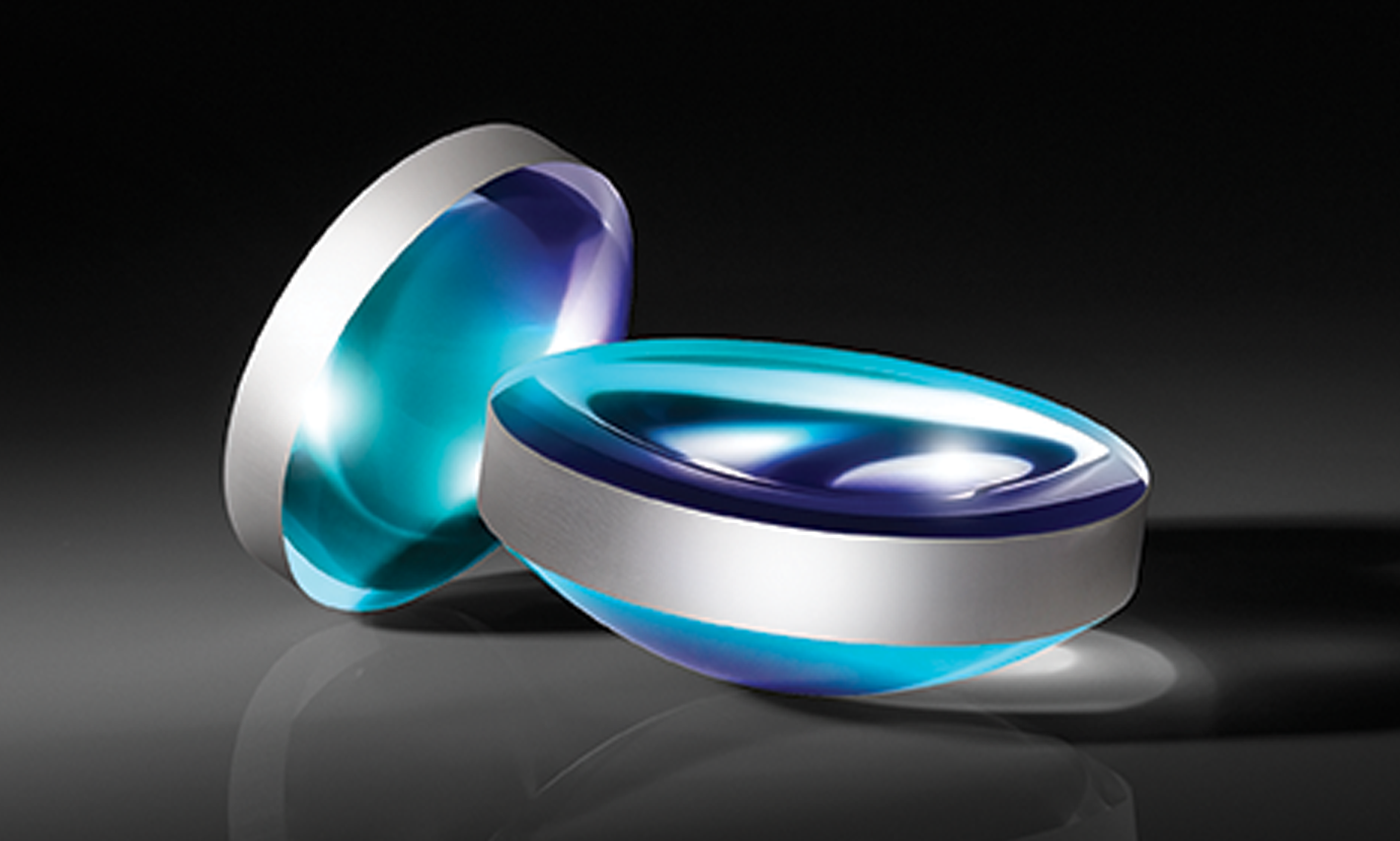
- Sizes up to 200mm in Diameter
- Available Uncoated or with Broadband Antireflection Coatings
BUY NOW
Custom Aspheric Lenses
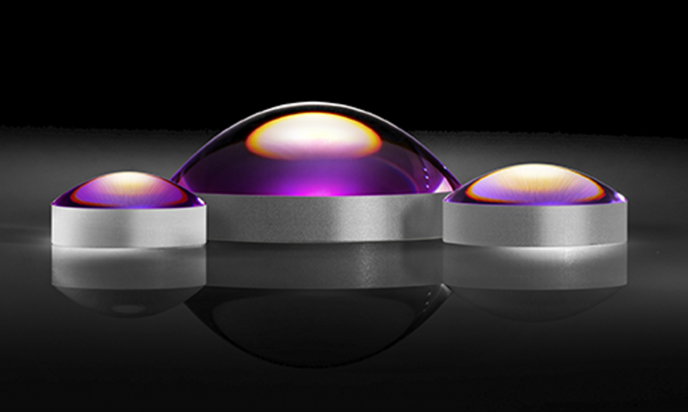
- Our Engineers can Walk You Through the Above Considerations
- What Can We Make for You?
CONTACT US
More Resources
- How an Aspheric Lens is Made Video
- All About Aspheric Lenses
- High-End Asphere Design for Manufacturability Webinar Recording
- Aspheric Lens Irregularity and Strehl Ratio
- Aspherized Achromatic Lenses
- Edmund Optics Global Manufacturing Facilities Video
- Metrology at Edmund Optics: Measuring as a Key Component of Manufacturing Video


or view regional numbers
QUOTE TOOL
enter stock numbers to begin
Copyright 2023, Edmund Optics India Private Limited, #267, Greystone Building, Second Floor, 6th Cross Rd, Binnamangala, Stage 1, Indiranagar, Bengaluru, Karnataka, India 560038
California Consumer Privacy Acts (CCPA): Do Not Sell or Share My Personal Information
California Transparency in Supply Chains Act