


Ruggedization of Imaging Lenses
This is Section 5.3 of the Imaging Resource Guide.
Imaging lenses used in industrial machine vision applications have special requirements beyond those of standard imaging lenses. The lenses used in factory automation, robotics, and industrial inspection must work in specific, demanding environments involving vibration, shock, temperature change, and contaminants. As such, new classes of ruggedized lenses have been designed to work specifically in a multitude of different scenarios. There are four distinct types of ruggedization available:
Industrial Ruggedization
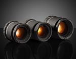
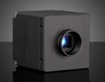
Industrial ruggedized lenses are designed to survive vibration and shock without taking damage or changing focus or f/#. Flexibility is sacrificed by eliminating moving parts to achieve this. A standard fixed focal length lens uses a focus mechanism and an iris that is comprised of thin leaves and ball detents to adjust f/# which can spring out of place during shock and vibration. The iris is removed and replaced with a fixed aperture stop in industrial ruggedized lenses and the focusing mechanism, typically consisting of a focusing mechanism of a threaded barrel within another threaded barrel, is replaced by a single thread and rigid lock mechanism.


Figure 1: A standard lens with complex mechanics and an adjustable iris vs. an industrial ruggedized lens with simplified mechanics.
Industrial ruggedization is ideal for applications where the system will be set up once and not changed. An added cost advantage is also present in this type of lens due to the removal of the complex movements and adjustments, resulting in significant part reduction and cost savings. There are more applications for industrial ruggedization, such as high vibration factory environments, situations where the camera is rapidly accelerated, inspection systems where many similar camera setups are repeated, and robotic vision.
Ingress Protection Ruggedization
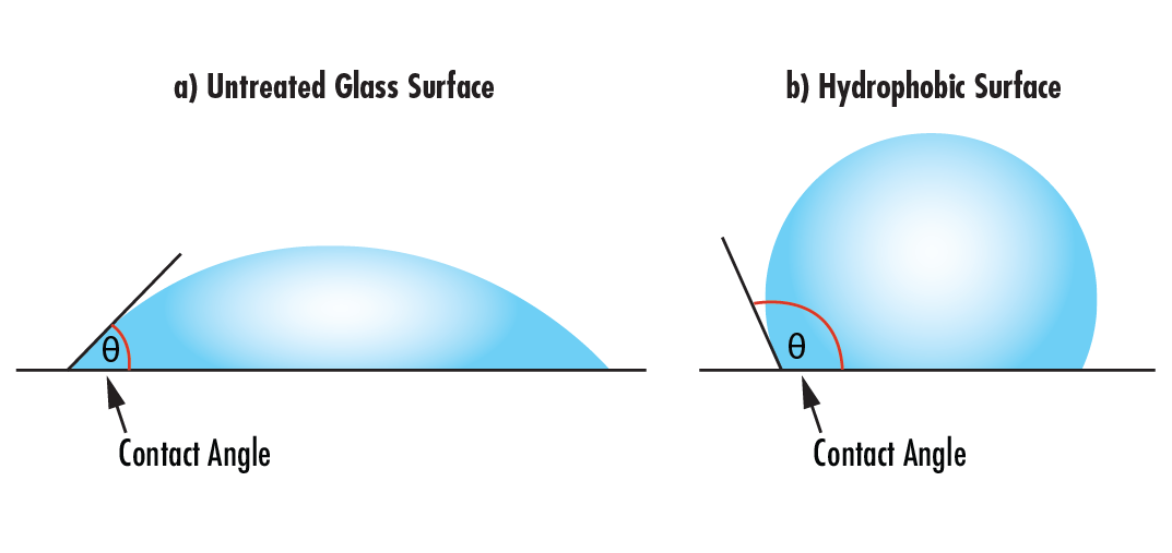
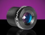
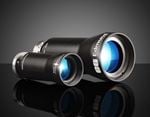
Ingress protection ruggedization ensures a lens assembly is sealed using O-rings to prevent moisture and debris from entering the lens. This protection is typically added to an industrial ruggedized lens as sealing an adjustable focus and iris would be problematic. These lenses are used in environments of high humidity/moisture, sputter, dust, or small particles, and where space to fully enclose the lens and camera is not available.
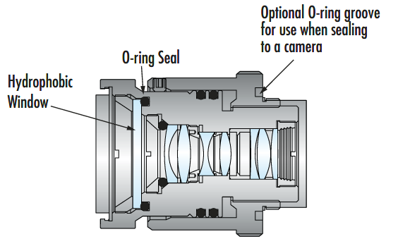
Figure 2: An ingress protected ruggedized lens features an O-ring to seal out contaminants like dust, dirt, or moisture and a hydrophobic window at the front of the optical train.
Ingress protection is specified with two digits, which make up the IP rating according to the IEC 60529 standard. The first digit describes the level of protection against solids and particles and ranges from zero to six. If a component has not been tested for protection against solid intrusion, the first digit is changed to an X (Table 1).
| Solid protection digit: | Description |
| X |
Testing for protection has not explicitly been conducted |
| 0 |
No protection from solid objects |
| 1 |
Protection from objects 50mm in diameter or greater |
| 2 |
Protection from objects 12.5mm in diameter or greater |
| 3 |
Protection from objects 2.5mm or greater |
| 4 | Protection from objects 1mm in size or greater |
| 5 | Partial protection from dust such that intrusion does not interfere with operation |
| 6 | Completely dust tight |
Table 1: The first digit of the IP rating describes the amount of protection an enclosure has from solids.
The second digit describes the protection from moisture and ranges from zero to nine (Table 2).
| Moisture protection digit: | Water Type | Description |
| X |
— |
Testing for protection has not explicitly been conducted |
| 0 | No protection from moisture | |
| 1 | Dripping | Protection from vertically falling droplets tested for 10 minutes |
| 2 | Protection from water droplets deflected up to 15° from vertical for 10 minutes | |
| 3 | Splashed or sprayed | Protection from water sprayed up to 60° from vertical |
| 4 | Protected from water splashes from all directions, tested for a minimum of 10 minutes | |
| 5 | Jet spray (pressurized) | Protection from low-pressure jets 6.3mm in diameter |
| 6 | Protection from direct pressure jets 12.5mm in diameter | |
| 7 | Continous Immersion | Protection from full immersion for up to 30 minutes at a depth between 15cm and 1m |
| 8 | Protection from extended immersion under higher pressure from depths greater than 1m | |
| 9 or 9K | High-pressure and-high temperature jet spray | Complete moisture protection from high-pressure, high-temperature jets, wash downs, and steam cleaning |
Table 2: The second digit of the IP rating describes the amount of protection an enclosure has from moisture.
Note that these ratings are not cumulative. Compliance with IPX7 or IPX8 does not guarantee IPX5 or IPX6 compliance. Products that comply with both a jet spray rating and a continuous immersion will be specified with both ratings. For example, the waterproof TECHSPEC® Cw Series Fixed Focal Length Lenses are IPX7 and IPX9K rated.
Stability Ruggedization
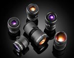
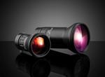
Like industrial ruggedized lenses, stability ruggedization protects the lens from damage, but also ensures optical pointing and positioning is maintained after shock and vibration. In addition to replacing the iris and a simplified focus mechanism, individual lens elements are glued in place to prevent them from moving within the housing. Figure 3 shows a stability ruggedized lens in which the lens elements are glued in place and a clamping lock is used to simplify the focus.

Figure 3: Stability ruggedized lens with all lens elements glued in place.
Lens elements sit within the inner bore of the barrel of an imaging assembly. The space between the outer diameter of the lens and inner diameter of the barrel is typically less than 50 microns. Despite the minimal amount of space, decenters, on the order of tens of microns are enough to significantly affect the pointing of the lens. When using a stability ruggedized lens, if an object point is in the center of the FOV and falls on the exact center pixel, it will always fall there even if the lens has been heavily vibrated (Figure 4). Stability ruggedization is important in applications where the FOV must be calibrated, such as measurement equipment, 3D stereo vision, lenses used for sensing in robotics, and lenses used for tracking object locations. These applications often require the optical pointing to be stabilized to values much smaller than a single pixel.


Figure 4: An unperturbed system where object crosshair is mapped to the image crosshair (a) and a perturbed system where lenses are decentered within the barrel and the optical pointing stability changes (b). The object crosshair is mapped to a different place (yellow) on the image than the unperturbed image (red). This example is highly exaggerated and actual changes tend to be on the order of a pixel or less.
Athermalization
Matter expands and contracts in response to temperature changes. The coefficient of thermal expansion (CTE) is a measure of how much a material changes in size. High-performance vision systems subjected to extreme or wide shifts in temperature require athermalized imaging lenses to minimize temperature-dependent performance changes. Athermalization refers to the process by which an optomechanical system is stabilized to extreme or changing temperatures, and also describes the optomechanical system that underwent the process. For more information on the optothermal and optomechanical effects of temperature on material expansion and the refractive index, read Thermal Properties of Optical Substrates.
Athermalization can be active or passive. Active athermalization results in a lens which has been designed and manufactured to withstand extreme or changing temperatures but may require additional intervention such as refocusing. Passive athermalization results in a lens which has been designed and manufactured with complementary materials to not need adjustment over the designated temperature range specification. Additional information about passive athermalization can be found in An Introduction to Passive Athermalization.
or view regional numbers
QUOTE TOOL
enter stock numbers to begin
Copyright 2023, Edmund Optics India Private Limited, #267, Greystone Building, Second Floor, 6th Cross Rd, Binnamangala, Stage 1, Indiranagar, Bengaluru, Karnataka, India 560038
California Consumer Privacy Act (CCPA): Do Not Sell or Share My Personal Information
California Transparency in Supply Chains Act